CPU Detection Routine
The Sorbus Computer can run any kind of 6502 variant that shares the same pinout. The small test and learn environment "Monitor Command Prompt" or MCP for short (pun very intended) can be used to learn all the details about each CPU up to a certain degree. (Not all pins are connected due to a limited amount of 30 GPIO pins on the RP2040.)
However, it is interesting to know which CPU the system is running on. The "JAM Core" is the one with the most features, but does use opcodes and features that are not available or buggy on an (old) NMOS 6502. This means that a 65C02 or any other CMOS variant is required. So, it should be a good idea to detect the NMOS 6502 and print an error message that the system won't work, when running on an NMOS 6502, instead of randomly crashing. (It even drops you to WozMon after acknowledging the error message, so that some very basic things can be done.)
Also, there is another point where a CPU detection is very handy. If you search for cheap 65C02 processors, you typically find offerings on ebay or AliExpress for WDC W65C02S processors. However, none of those are original ones, but all of those are pulled out of machines, and then get relabeled. (At least the ones I've seen so far.) For this project using those would not be that bad, if they would not throw in NMOS 6502s in the mix as well. Those, as explained above, don't fit the requirements.
Finally, there is also another reason to try this: for the challenge. After all, this is something where there isn't a solution available on the internet in several variants.
And the solution presented here is also not one without side effects, as it relys on special features of the runtime environment. This exact code would only work partially on an Apple II series machine for example.
Partial Detection
A very easy way to tell apart an NMOS 6502 CPU from it's CMOS successors it done like this in the Sorbus JAM kernel.
;  65C02       ; NMOS 6502
   LDA   #$00  ; LDA   #$00
   DEC         ; .byte $3a  ; "illegal" NOP
   BNE   CMOS  ; BNE   CMOS ; NMOS will not take the branch
In the above case DEC will be assembled to $3A which is an undocumented
(also called "illegal") NOP opcode. So, while the LDA #$00 sets the
zero-flag, it will be cleared by the DEC opcode, but not by the "illegal"
NOP opcode. This also works the same with the INC ($1A) Opcode as well.
So, this is a short and efficiant way to tell NMOS and CMOS variants apart,
as all CMOS variants share the same INC/DEC instructions. This is the
detection the "JAM Core" kernel uses for locking out the NMOS 6502.
On the internet, I found a solution on how to detect the three major CPUs: NMOS 6502, CMOS 65C02 and the 65816, the variant with 16 bit extensions. This was most probably used to tell apart an Apple IIgs (using a 65816) from an Apple IIc/IIe enhanced (using a 65C02) and the original Apple II/II+/IIe (using an NMOS 6502).
;  65816       ; 65C02            ; 6502
   LDA   #$01  ; LDA   #$01       ; LDA   #$01
   XBA         ; .byte $EB ; NOP  ; .byte $EB, $EA ; "illegal" SBC #$EA
   NOP         ; NOP              ;
   LDA   #$EA  ; LDA   #$EA       ; LDA   #$EA
   XBA         ; .byte $EB ; NOP  ; .byte $EB, $EA ; "illegal" SBC #$EA
   NOP         ; NOP              ;
;  A=$01       ; A=$EA            ; A=$00

;  ALL
   BEQ   is6502   ; needs to be first
   BPL   is65816
   BMI   is65c02  ; is obsolete if 65c02 specific code continues here
As you can see, just detecting three CPUs make things significantly more complex. Still, this routine is also quite clever with utilizing the CPU flags for easy branching to the CPU specific routines.
However, the opcode $EB on a 65CE02 is totally incompatible as it is
a read-modify-write opcode that even operates on two bytes (ROW).
This renders this routine useless when a 65CE02 is encountered.
Now there are two ways. Either to check for the 65CE02 in advance or start from scratch.
The Goal
The goal is to could tell 6502 variants apart by their instruction sets. There are five different instruction sets have been seen in chips with a pin layout similar to the original NMOS 6502 and the CMOS 65C02:
- NMOS 6502 (Rev.D)
- however, there is the NMOS 6502 Rev.A, the first 6502 that was still missing the ROR opcodes
- 65C02, the base CMOS variant, as compared to the NMOS version, a couple of bugs were fixed, and new instructions were introduced
- 65SC02, a 65C02 with the bit-related opcodes removed ($x7 and $xF are just 1 byte, 1 cycle NOPs), STP and WAI are missing as well
- 65816, a 16 bit capable variant of the 65SC02, with all 256 opcodes defined now
- 65CE02, a CMOS reimplementation of the 65C02 by Commodore with also 256 opcodes defined, but totally different compared to the 65816
The pin layout is not 100% the same on all chips, but still enough to run all CPUs with the Sorbus Computer, while omitting some of their features provided by pins on the chip. Variants like the HuC6280 are not part of conciderations, as those chips have totally different pin layouts.
Side note: the NMOS 6502 has 3510 transistors, the Rev.A should have a few less. The 65C02 and 65SC02 are told to have around 4000 transistors. The 65CE02 doubles that amount with about 8000, while the 65816 has whopping 22000 transistors. (If you can, please provide more exact numbers and also references.)
The Runtime Environment
To make things easier, a runtime environment was defined with the sole purpose to detect the CPU. This is the advantage of this software defined computer: you can use a special environment for detection and then switch over to a generic one.
The "runtime environment" is - as all other runtime environments like the previous mentioned MCP and JAM Cores - written in C. It provides everything up to the memory and clock signal. The running code to detect the CPU should write an identifier to the last byte of memory. If this value changes from the default one, the processing will be stopped.
Since the code will be rather simple, the environment provided should also be rather simple. Except from the "return value" no I/O is required. Memory used can also be kept very low: 32 bytes have been proven to be enough, if the memory is "wrapped around" by not fully decoding the address. The code size is just 30 bytes, but the amount of memory provided needs to be a power of 2, as implementing this differently does not make sense.
The "result-byte" written to the end of memory will then be evaluated. If it is in the defined range, the processor type id will be returned by the runtime environment, otherwise a zero indicates a failure.
The "runtime environment" also comes with another feature. Since it's well encapsulated, it can be used just as a subroutine in differenct cores. As of now, it is used within the MCP and the JAM Core.
Every Byte Is Sacred
One of the fun things about coding for a 6502 processor is trying to reach a maximum of efficiency. This typically means: either to use a minimum amount of CPU clock cycles or a minimum amount of bytes of code. This code focuses on the latter.
The basic idea for supplying the return code is a slide of INX
opcodes, which then writes the result to the exit code address ($FF).
But for this to work, X has to be initialized to $00.
So the code would pratically look something like this:
   LDX   #$00 ; clear out X
   ; run test code
   ; [...]
   ; more return codes before those three
is65816:      ; exit for 16 bit 65816 (3)
   INX
is65C02:      ; exit for CMOS 65C02 (2)
   INX
is6502:       ; exit for NMOS 6502 (1)
   INX
   STX   $FF  ; stops runtime environment
This way, if a specific CPU was detected, jumping to the matching label will then return the proper code.
The last six bytes in memory are vectors for NMI, reset and IRQ (in this order). However, as we are not using neither the NMI nor the IRQ, those memory addresses can be used for code as well. So our code starts at the IRQ vector, and then wraps around as described above to address $0020.
The Detection Routine
The source code is complex, as it was written for all architectures at the same time.
   ; should start at $0000
   ; whole memory is just $20 (=32) bytes
   ; -> code also needs to be 32 bytes
   ; runtime environment is also not capable of generating IRQ or NMI
start:
   ;ldx   #$00 ; removed due to reset vector now at irq and code is wrapping
   clc
   ; $5c is evaluated by ($xxxx = address of is65816):
   ; 6502:     NOP $xxxx,X ("illegal" opcode)
   ; 65(S)C02: NOP #$xxxx (reserved)
   ; 65816:    JMP $38xxxx ($38 taken from SEC)
   ; 65CE02:   AUG #$38xxxx ($38 taken from SEC)
   .byte $5c
   .word is65816
   ; 6502 and 65(S)C02 continue here from $5c
   sec
   ; 65CE02 continues here from $5c
   bcc   is65CE02
   txa           ; A=$00
   ; $1a is evaluated by:
   ; 6502:   NOP ("illegal" opcode)
   ; 65C02:  INC
   .byte $1a
   bne   check65sc02  ; 6502: A=$00, 65(S)C02: A=$01
   ror
   bcs   is6502noror
   bcc   is6502
check65sc02:
   ; $97 is evaluated by:
   ; 65C02:  SMB1 $FF ; will set retval to $02 = 65C02
   ; 65SC02: NOP(reserved) : NOP(reserved, $FF)
   .byte $97
   .byte $FF

is65SC02:
   inx            ; X=$06
is6502noror:
   inx            ; X=$05
is65CE02:
   inx            ; X=$04
is65816:
   ; 65816 continues here from $5c
   inx            ; X=$03
is65C02:
   inx            ; X=$02 ; will be set using SMB1 $FF above
is6502:
   inx            ; X=$01
   stx   $ff      ; will stop CPU

   .byte $ea,$4c  ; spare bytes, unused, evaluate to NOP : JMP irq
                  ; also NMI vector, which is also unused
reset:
   .word irq      ; reset vector, start of ram
irq:
   ldx   #$00     ; argument needs to be $00
   ;slip through to start
Because reading the source code is very hard, as you can't write code for different variants at the same time, let's use a simple flow chart on how the detection is implemented. Red bubbles show a successful detection of a CPU variant.
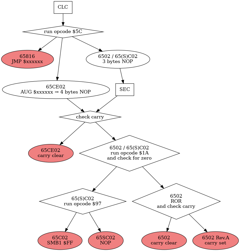
Detection Routine As Processed By The Different CPUs
Now, we can also take a look at the traces collected from running all those CPUs.
Hexdump
This is the initial memory configuration when starting the detection environment.
0000: 18 5c 15 00 38 90 0d 8a 1a d0 05 6a b0 05 90 07  .\..8......j....
0010: 97 ff e8 e8 e8 e8 e8 e8 86 ff ea 4c 1e 00 a2 00  ...........L....
Let's start by taking a look at the last six bytes, the vectors described
above. The reset vector points to the last two bytes of memory ($001E),
which holds the first instruction. The two bytes before the NMI vector
($0018) hold the STX $FF instruction that will stop the runtime
environment. Even though the bytes for the NMI vector ($001a) shouldn't
be processed, they contain same sane data, a NOP opcode and the opcode for
JMP, this way using the reset vector as an address, this way restarting
the code. This ensures that when something does go wrong, the system does
not drift into undefined behaviour.
Before we dive into the disassemblies, first let's explain the format using the first executed instruction as our example.
10:001e r a2 :LDX #$00
The 10 is just a line number. Counting starts when the reset line is
pulled high, so the CPU leaves reset state. Code execution starts with
the instruction after reading the reset vector at $FFFC/$FFFD, which
is also the first line with disassembly.
This is followed by an overview of the bus state at that time. 001e is
the address bus, r shows that the CPU is reading, and a2 is the data
bus, showing what was read (or written). If lines like Reset, NMI or IRQ
are triggered by pulling to GND, that would be also shown by a
corresponding letter.
LDX #$00 is the disassembly of the instruction starting at this
memory address. (In this case "LoaD the X register with the value of
$00".) A dot behind the opcode (like: NOP.) indicates that the opcode
is a reserved (CMOS) or undocumented (NMOS) one. Not every line has a
disassembly, because opcodes typically use more than a single cycle to
execute.
Every trace should end with a 00ff w XX, which indicates the writing
of the CPU id at the "end of memory". This also stops the runtime
environment.
The disassemblies were created with the command cold debug of the MCP
core. They have been slightly modified for a better readability. (As of
writing this document, the disassembler can't always tell apart if the
byte read is an opcode or a parameter.)
Disassembly as seen on a 6502
  1:8aff r 00    :
  2:0089 r d0    :
  3:d0ff r 00    :
  4:d0ff r 00    :
  5:0100 r 18    :
  6:01ff r 00    :
  7:01fe r a2    :
  8:fffc r 1e    :
  9:fffd r 00    :
 10:001e r a2    :LDX  #$00
 11:001f r 00    :
 12:0020 r 18    :CLC
 13:0021 r 5c    :
 14:0021 r 5c    :NOP. $0015,X
 15:0022 r 15    :
 16:0023 r 00    :
 17:0015 r e8    :
 18:0024 r 38    :SEC
 19:0025 r 90    :
 20:0025 r 90    :BCC  $0034
 21:0026 r 0d    :
 22:0027 r 8a    :TXA
 23:0028 r 1a    :
 24:0028 r 1a    :NOP.
 25:0029 r d0    :
 26:0029 r d0    :BNE  $0030
 27:002a r 05    :
 28:002b r 6a    :ROR
 29:002c r b0    :
 30:002c r b0    :BCS  $0033
 31:002d r 05    :
 32:002e r 90    :BCC  $0037
 33:002f r 07    :
 34:0030 r 97    :
 35:0037 r e8    :INX
 36:0038 r 86    :
 37:0038 r 86    :STX  $FF
 38:0039 r ff    :
 39:00ff w 01    :
This is the exact CPU variant used in most machines in the late 1970s
and early 1980s. The $5c used in line 14 to detect the 65816 and 65CE02
is skipped and the INC-test in line 24 for any CMOS variant does also
not succeed. The third and final test in line 28 for a working ROR
instruction does succeed, though.
Disassembly as seen on a 6502 Rev.A
This is just estimated, as such a processor is hard to find for a decent price.
  1:8aff r 00    :
  2:0089 r d0    :
  3:d0ff r 00    :
  4:d0ff r 00    :
  5:0100 r 18    :
  6:01ff r 00    :
  7:01fe r a2    :
  8:fffc r 1e    :
  9:fffd r 00    :
 10:001e r a2    :LDX  #$00
 11:001f r 00    :
 12:0020 r 18    :CLC
 13:0021 r 5c    :
 14:0021 r 5c    :NOP. $0015,X
 15:0022 r 15    :
 16:0023 r 00    :
 17:0015 r e8    :
 18:0024 r 38    :SEC
 19:0025 r 90    :
 20:0025 r 90    :BCC  $0034
 21:0026 r 0d    :
 22:0027 r 8a    :TXA
 23:0028 r 1a    :
 24:0028 r 1a    :NOP.
 25:0029 r d0    :
 26:0029 r d0    :BNE  $0030
 27:002a r 05    :
 28:002b r 6a    :ROR.
 29:002c r b0    :
 30:002c r b0    :BCS  $0033
 31:002d r 05    :
 32:002e r 90    :
 33:0033 r e8    :INX
 34:0034 r e8    :
 35:0034 r e8    :INX
 36:0035 r e8    :
 37:0035 r e8    :INX
 38:0036 r e8    :
 39:0036 r e8    :INX
 40:0037 r e8    :
 41:0037 r e8    :INX
 42:0038 r 86    :
 43:0038 r 86    :STX  $FF
 44:0039 r ff    :
 45:00ff w 05    :
This is almost the same as before (6502), except that the ROR
instruction in line 28 does not modify the carry flag, like it
was supposed to. So this has to be one of those early and rare
6502s with the ROR-instruction missing. (Note the dot after
the ROR.)
For more details on this topic, I recommend watching the video "The 6502 Rotate Right Myth" by Eric Schlaepfer, who also built the MOnSter 6502.
Disassembly as seen on a 65C02
  1:0032 r e8    :
  2:0032 r e8    :
  3:ffff r 00    :
  4:0033 r e8    :
  5:01f7 r e8    :
  6:01f6 r e8    :
  7:01f5 r e8    :
  8:fffc r 1e    :
  9:fffd r 00    :
 10:001e r a2    :LDX  #$00
 11:001f r 00    :
 12:0020 r 18    :CLC
 13:0021 r 5c    :
 14:0021 r 5c    :NOP. #$0015
 15:0022 r 15    :
 16:0023 r 00    :
 17:ff15 r e8    :
 18:ffff r 00    :
 19:ffff r 00    :
 20:ffff r 00    :
 21:ffff r 00    :
 22:0024 r 38    :SEC
 23:0025 r 90    :
 24:0025 r 90    :BCC  $0034
 25:0026 r 0d    :
 26:0027 r 8a    :TXA
 27:0028 r 1a    :
 28:0028 r 1a    :INC
 29:0029 r d0    :
 30:0029 r d0    :BNE  $0030
 31:002a r 05    :
 32:002b r 6a    :
 33:0030 r 97    :SMB1 $FF
 34:0031 r ff    :
 35:00ff r 00    :
 36:00ff r 00    :
 37:00ff w 02    :
The way the $5c opcode at line 14 is processed here looks a bit strange.
For a couple of cycles (lines 17-21), the CPU seems to have stopped
working, like when an NMOS 6502 executes a KIL (illegal) opcode.
However at some point the CPU just continues working at line 22. So this
behaviour is very different from the way the NMOS 6502 processes this
opcode. The result is the same, though: a three-byte NOP.
But when testing for an implemented INC instruction at line 28, it
succeeds this time. Then one of the bit manipulation instructions in line
33, which is not present on the 65SC02, sets the bit 1 of the return
value, at line 37 making this the only time, the INX-slide is not used
for the return value.
Disassembly as seen on a 65SC02
  1:0001 r 5c    :
  2:0001 r 5c    :
  3:0001 r 5c    :
  4:0100 w 00    :
  5:01ff w 01    :
  6:01fe w 62    :
  7:fffc r 1e    :
  8:fffd r 00    :
  9:001e r a2    :LDX  #$00
 10:001f r 00    :
 11:0020 r 18    :CLC
 12:0021 r 5c    :
 13:0021 r 5c    :NOP. #$0015
 14:0022 r 15    :
 15:0023 r 00    :
 16:ff15 r e8    :
 17:ffff r 00    :
 18:ffff r 00    :
 19:ffff r 00    :
 20:ffff r 00    :
 21:0024 r 38    :SEC
 22:0025 r 90    :
 23:0025 r 90    :BCC  $0034
 24:0026 r 0d    :
 25:0027 r 8a    :TXA
 26:0028 r 1a    :
 27:0028 r 1a    :INC
 28:0029 r d0    :
 29:0029 r d0    :BNE  $0030
 30:002a r 05    :
 31:002b r 6a    :
 32:0030 r 97    :NOP.
 33:0031 r ff    :NOP.
 34:0032 r e8    :INX
 35:0033 r e8    :
 36:0033 r e8    :INX
 37:0034 r e8    :
 38:0034 r e8    :INX
 39:0035 r e8    :
 40:0035 r e8    :INX
 41:0036 r e8    :
 42:0036 r e8    :INX
 43:0037 r e8    :
 44:0037 r e8    :INX
 45:0038 r 86    :
 46:0038 r 86    :STX  $FF
 47:0039 r ff    :
 48:00ff w 06    :
This the same as before (65C02), except that the bit set instruction is
interpreted as a reserved NOP. opcode in lines 32. It's the same with
the address of that instruction at line 33. So execution continues with
the INX-slide.
Disassembly as seen on a 65816
  1:001b r 4c    :
  2:001b r 4c    :
  3:001b r 4c    :
  4:01ee r 90    :
  5:01ed r 05    :
  6:01ec r b0    :
  7:fffc r 1e    :
  8:fffd r 00    :
  9:001e r a2    :LDX  #$00
 10:001f r 00    :
 11:0020 r 18    :CLC
 12:0021 r 5c    :
 13:0021 r 5c    :JMP  $380015
 14:0022 r 15    :
 15:0023 r 00    :
 16:0024 r 38    :
 17:0015 r e8    :INX
 18:0016 r e8    :
 19:0016 r e8    :INX
 20:0017 r e8    :
 21:0017 r e8    :INX
 22:0018 r 86    :
 23:0018 r 86    :STX  $FF
 24:0019 r ff    :
 25:00ff w 03    :
This is a straight forward one. The 65816 interprets the $5c opcode in line 13 as a JMP to a 24 bit address. Since we're wrapping around most of the address does not matter much, only the least significant byte is required here.
Disassembly as seen on a 65CE02
  1:01f8 r 86    :
  2:01f8 r 86    :
  3:01f8 r 86    :
  4:01f7 r e8    :
  5:01f6 r e8    :
  6:fffc r 1e    :
  7:fffd r 00    :
  8:001e r a2    :LDX  #$00
  9:001f r 00    :
 10:0020 r 18    :CLC
 11:0021 r 5c    :AUG  $380015
 12:0022 r 15    :
 13:0023 r 00    :
 14:0024 r 38    :
 15:0025 r 90    :BCC  $0034
 16:0026 r 0d    :
 17:0034 r e8    :INX
 18:0035 r e8    :INX
 19:0036 r e8    :INX
 20:0037 r e8    :INX
 21:0038 r 86    :STX  $FF
 22:0039 r ff    :
 23:00ff w 04    :
This CPU is very interesting. Notice how the INX opcodes in lines
17-20 are all processed within a single clock cycle. No other 6502
variant can do this, they all require two clock cycles.
The rest of the detection is rather plain. The $5c opcode in line 11 is evaluated as a 4 bytes instruction. The only 4 byte opcode this CPU has. Only the 65816 also has 4 byte opcodes.
This opcode however, even though it is called AUG, behaves like a
4 byte NOP. So, in this case the SEC, that's evaluated by all other
CPUs (except for the 65816), is skipped, and the BCC-branch is taken
by this CPU only. (The 4510 chip uses the $5c opcode, now called MAP
and shrunken down to 1 byte, to set up memory mapping. Also note that
branching requires only two clock cycles, not three like with all other
6502 variants.)
The Mysterious Problem
Since the start of a CPU detection within the Sorbus Computer, sometimes a CPU could not be detected, but when running the test a couple of times, it then magically worked.
What has happend? Typically when processing the reset, the CPU does some dummy reads from the stack. However, take a look at lines 4-6 from the 65SC02 disassembly. On some CPUs, these dummy reads are actually dummy writes. This destroys three subsequent bytes in memory. The start must be concidered random, as the stackpointer is not reset yet. But after that the stackpointer seems to just stay where it was, moving by three bytes each reset. So during the retries, the stackpointer gets moved to a position, where the writes go to a part of memory that was not used during the test.
Interestingly, this is described as an enhancement to the original NMOS 6502 CPU according to the CMD G65SC02 datasheet. However, even later CPUs do not have this "feature". It is also not possible to cleanly "return" from a reset, since the program counter might not be pointing to an instruction. This is not the case with interrupts.
How was it fixed? The writes happen in a very early stage, even before the reset vector is being read to determine where in memory to start executing code. So, writes are now discared, if they were done before reading the reset vector. Or one can say: before the reset vector is read the memory is read-only. Problem solved with an elegant solution.
There Is Always Someone Better
After finishing the CPU detection from the Sorbus, I found this: getspu.s of the cc65 compiler suite. It can tell apart nine different 6502 based CPUs.
While there are more than the six CPUs being detected with the method described here, it does not make sense to add any of those CPUs to this routine for a simple reason: they don't fit in a 40 pins socket compatible with the 65C02. The table has a slightly more detailed description:
| CPU | Description | Supported in Sorbus |
|---|---|---|
| NMOS 6502 | original 6502 | yes |
| 65C02 | "current" 6502 still being sold | yes |
| 65816 | 16-bit variant still being sold | yes |
| 65SC02 | 65C02 without bit manipultion opcodes | yes |
| 65CE02 | Commodore CMOS, used in Amiga A2232 | yes |
| 4510 | 65CE02 based microcontroller with MMU | no, different package |
| 45GS65 | MEGA65, huge expansion of 4510 | no, FPGA |
| HuC6280 | PC Engine, CMOS, adds MMU and sound | no, different package |
| 2a03/2a07 | NES/Famicom, NMOS, adds sound, no BCD | no, different pinout |
So, there is no other CPU to be detected.
However, getcpu.s does not support the 6502 without the ROR opcode.
As the output of the C compiler relies on this opcode, it does not make
sense to add this detection to a library function. The code will most
probably crash before running this function. The Sorbus JAM on the other
hand will fall back to a machine language monitor that is implemented
without using any ROR opcodes, so the Rev.A CPU can be experimented
with. If you can find one.